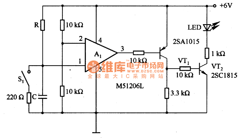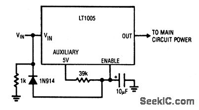

Time relay is an automatic control electrical appliance that uses the principle of electromagnetic or mechanical action to delay the closing or opening of contacts. In many control systems, use the time relay to achieve delay control. The time relay is a very important component in the electrical control system. Ⅰ Time Relay Basics 1.1 What is a Time Delay Relay?

Ⅸ Frequently Asked Questions about Time Delay Relay Basics Ⅷ Case Study: Time Relay Switch in Light Circuit I haven't tested a circuit like this but its something to ponder.Ⅱ Understanding Time Delay in Relay Circuitħ.2 Two Points for Attention in Using Time Relays In this case if the circuit stops receiving pulses from the computer, the 555 will not be reset and will shut off, cutting the signal to this circuit and then to the SSR(if I remember the workings of the 555 properly). A better circuit might be something like a 555 timer in one-shot mode and using the computer to continually reset the chip to keep the circuit on.
Power on time delay circuit software#
In your case, however, I'm not sure that this circuit, as is, would be the best fit considering, in the event of a software malfunction, there is a possibility that the signal pin driving this circuit can remain high until the power is removed from the computer (I've had it happen before) and this will prevent the circuit from turning off. One word of warning though: the delay time is also greatly affected by the maximum input voltage of the signal, which with a few more components could actually be a crude ADC (it already kind of is), and length of the pulse. The delay can be tuned by changing the size of either the resistor, capacitor, or both, although a smaller capacitor and a higher value resistor will result in less current being drawn to drive it (not like it takes much to drive it anyways haha), also a 100k pot could be used in place of the 47k resistor for fine tuning. Yes as long as the voltage on the capacitor doesn't drop below a certain point, the circuit will remain on.

Thanks in advance, great work, I enjoyed going over your other work, you would make a good teacher :). What I am looking for is a delay before power off the circuit is energized which energizes another circuit and the delay starts for about 30-45 seconds, then after the delay the other circuit is de-energized while power is still being supplied to the timing circuit, hope it's clear. Is the MOSFET a different type/version? I am having problems getting the circuit to work and don't have enough knowledge to troubleshoot. In the photos you have the resistor coming from the capacitor connected to pin 1, Pin 2 is connected to V+ in the top row, and "Signal Out" to pin 3. Below is a pin-out diagram, it shows pin 1 as the Gate, 2 as the Drain, and pin 3 as the Source.

Step 2 you have a schematic that shows MOSFET IRF3205, in the photos showing the assembly of the MOSFET is puzzling. I'm trying to learn about time delays, while trying to study your circuit i am unable to understand a couple of items, maybe you could explain. Thanks for the instructable, very simple and easy and very well explained. Like what you see here? Consider supporting me on Patreon. This action would be handy for running electronic devices that can't really tolerate the in between voltages very well such as an induction motor driven pump (AC) or an inverter (DC). What the relay does is act as a type of quasi schmitt trigger and provides a nice transition from on to off without fading by breaking the contacts when the output from the transistor hits a certain voltage. The resistor connected to ground slowly drains the capacitor of it's charge and when the capacitor reaches a certain voltage, the transistor fades out and shuts off. The way this circuit works is when the signal in, line goes high and charges up the capacitor and turns on the transistor. Apply power and push the button, if it lights up for a short time then fades out, the circuit is working properly and you can now add the relay if you do so choose. Its now time to test the circuit and add the extras.Īdd a button connecting the positive rail to the signal in line and connect an LED and a resistor to the signal out line.


 0 kommentar(er)
